Geological CO2 storage · est. surface datum 0 m

Near-factory
CO2 storage.
Permanent.

We explore, build and operate geological CO2 sequestration sites next to the industries that need them. Local, safe and sustainable, with low exploration risk carried by you.

Europe Mainland South America South East Asia Australia

01 · The hard to abate emitter Factory
can’t move.

02 · The problem Emissions
can’t wait.

03 · The answer Deep underground.
CO2 stored permanently
& safely.

PLATE 01Industrial decarbonizationSHEET 01 / 09

Hard to abate does not
have to mean impossible.

Our clients across cement, steel, fertilizer, power generation, bioethanol, chemicals, lime, sugar and waste incineration are struggling to deploy proven and affordable decarbonization plans to slash their emissions. We deliver the geological exploration to build safe and viable CO2 sequestration sites near your industrial site, at no risk. Then we provide the long-term CO2 storage as a service to reach your net-zero objectives.

01

Off the fence storage

Dedicated CO2 storage built next to your plant, not thousands of kilometres away.

02

No exploration risk

We carry the subsurface risk of finding and proving the storage complex.

03

Predictability and control

You keep visibility and control over your own CO2 removal, tonne by tonne.

04

No greenwashing

A pure CO2 operator. Our prospects are never used for petroleum production.

The same tonne, two journeys

The hub model relies on long transport and on the dependence a single hub creates. Ours relies on the rock under your own site.

01 THE HUB MODEL CAPTURE, THEN MOVE THE TONNE REMOTE STORAGE THOUSANDS OF KILOMETRES 02 NEAR-FACTORY STORAGE MIN FOOTPRINT · MIN IMPACT CAPTURE, THEN STORE IN THE VICINITY A FEW METRES RETHINKING CARBON STORAGE FLIPPING THE MODEL SAME TONNE ON BOTH ROUTES DISTANCES AND SIZES NOT TO SCALE
Fig. 02 · The same tonne, two journeysNot to scale

The differential

Distance creates dependence.

Transport is the cost and the emissions that nobody puts in the brochure. Depending on storage that sits far away is the same weakness that dependence on imported energy is exposing today. Removing that distance is the whole reason we look for geology next to the emitter.

PLATE 02ScreeningSHEET 02 / 09

We start at your factory,
then dig into the rock.

Our core expertise, and the hardest part of our activity, is to find and confirm where CO2 geological storage can actually be deployed. Screening runs across three pillars, and a site only advances when all three agree.

01

Hard to abate industry mapping

Finding out where industries which benefit from CCS are ready to deploy it on the long term.

02

Geological suitability mapping

Finding out where the geological setting allows for permanent and safe CO2 storage.

03

Local acceptance mapping

Finding out where local cities, neighbours, authorities and industries see a value in deploying CCS.

Applicability

Find out if you can do it
at your factory.

If you make any of these, capture is not the open question. Whether the rock under your own site can take what you emit is. That is the part we answer, and we answer it before you transform your factory.

Ask about your site
  1. 01Cement
  2. 02Steel
  3. 03Fertilizer
  4. 04Power generation
  5. 05Bioethanol
  6. 06Chemicals
  7. 07Lime
  8. 08Sugar
  9. 09Waste incineration
  10. 10Hydrogen production
  11. 11Ammonia
  12. 12Glass
  13. 13Aluminium
  14. 14Pulp and paper
  15. 15Gypsum
  16. 16Direct air capture
Key · Industries we serve16 sectors
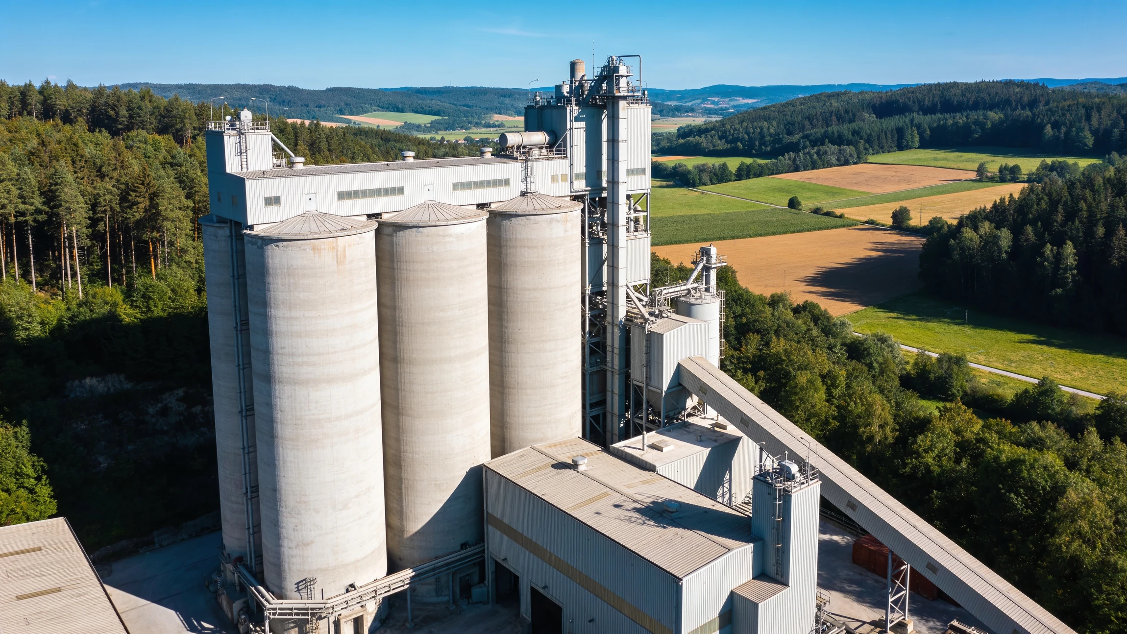
Aerial view of a cement works with concrete silos, bordered by forest and farmland
Fig. 03 · Cement, the emitter we screen around Reference imagery
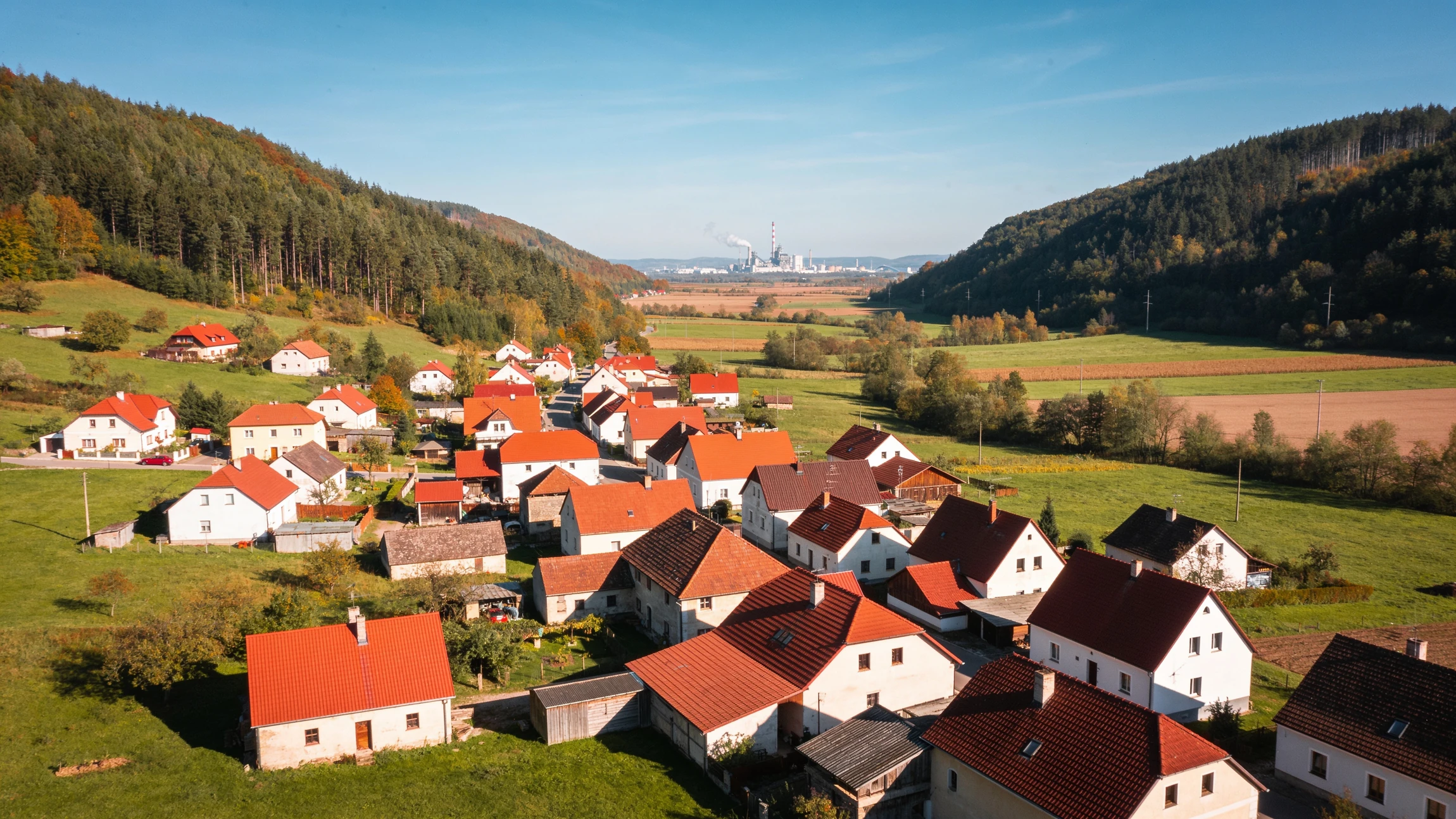
Aerial view of a village of red roofed houses in a green valley, forest on the hillsides and an industrial plant far away on the horizon
Fig. 04 · Local communities, not empty groundReference imagery
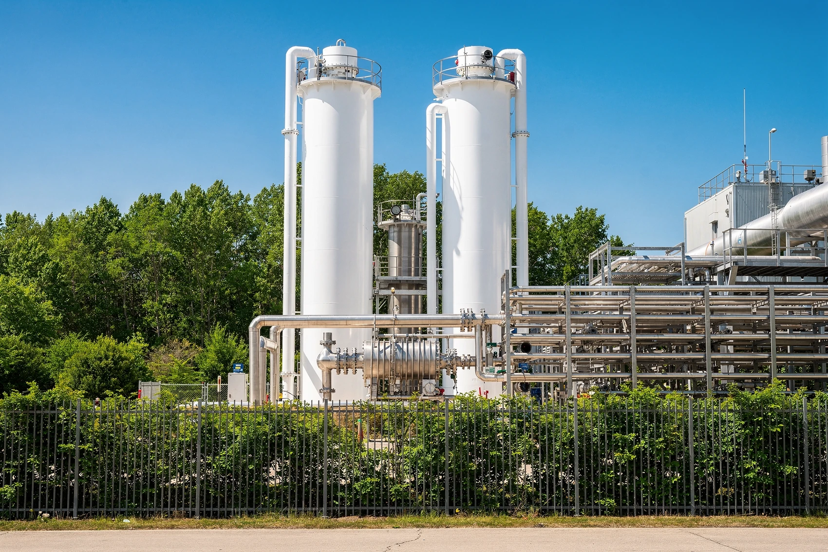
A carbon capture unit beside an industrial plant, tall white columns and pipe racks with trees immediately behind the fence
Fig. 05 · Capture at the plant, storage next doorReference imagery
PLATE 03ExplorationSHEET 03 / 09

A paradigm change in storage exploration.

We focus mainly on deep saline aquifer exploration, deeper than 1000 m. Identifying a portfolio of prospects linked with the industries that need it, we can deploy near-factory storage quickly: at low risk, cutting off expensive and low-sustainable CO2 transport.
  • Surface exploration with detailed geological studies and seismic survey.
  • Exploratory drilling for the sites that make the cut, with extensive data acquisition and rigorous testing on rock samples.
  • A proven robust sealing formation capable of structurally trapping CO2.
  • A permeable formation capable of accommodating the injection of CO2.
0 m · SURFACE OVERBURDEN MONITORING RESERVOIR SEAL FORMATION SALINE AQUIFER · BELOW 1000 m BASEMENT
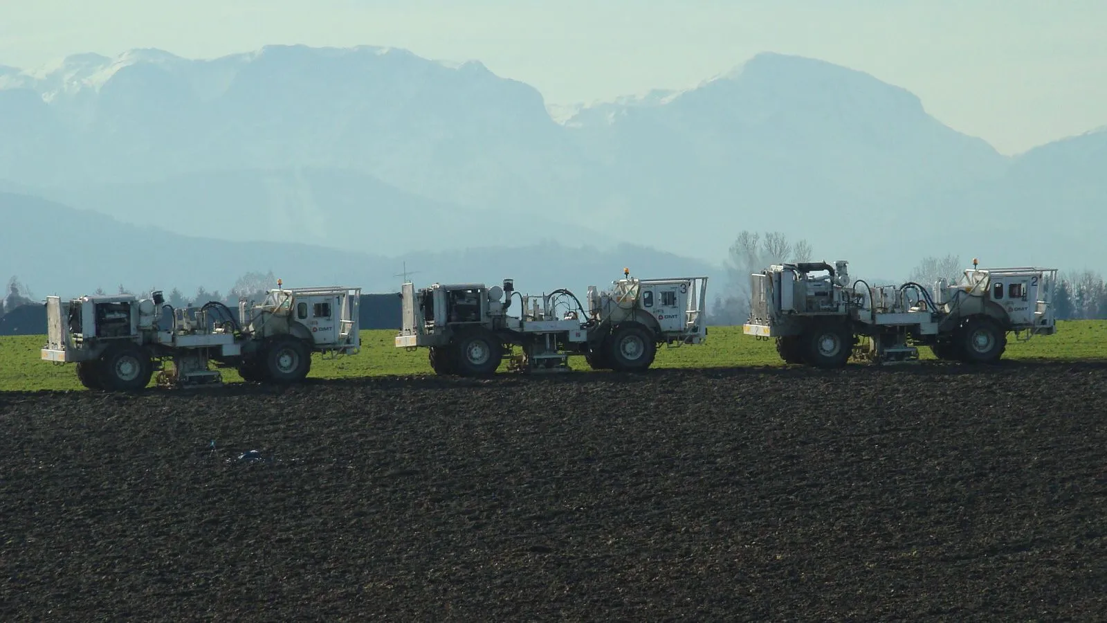
Three white vibroseis trucks crossing a ploughed field in the Alpine foothills of Upper Austria, snow capped mountains behind
Fig. 06 · Vibroseis seismic surveyPhoto

Photo: Techcollector · CC BY-SA 3.0 · cropped

Fig. 07 · Exploratory drilling Fig. 08 · Exploratory drilling · live log 0m Surface

The rig goes down once the seismic says the geology is worth the trip.
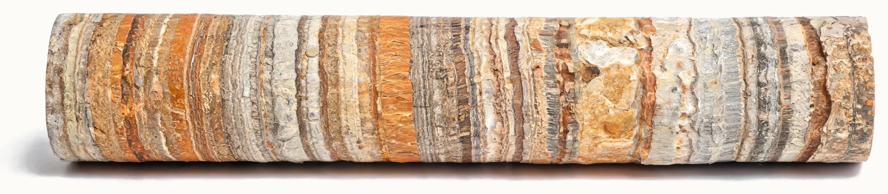
A cored section of layered sedimentary rock, alternating porous sandstone and tight carbonate bands
Fig. 09 · Core interval, alternating porous and sealing beds Reference imagery
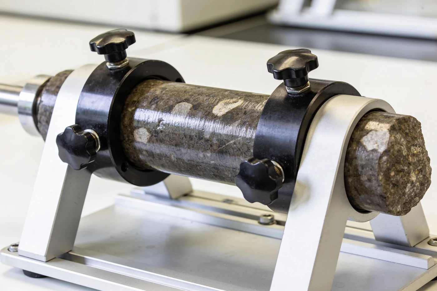
A rock core plug clamped inside a triaxial core holder on a laboratory bench, pressure lines and digital readouts behind it
Fig. 10 · Core sample under testingReference imagery
A cylindrical rock core plug clamped inside a laboratory core holder with pressure fittings
Fig. 11 · Core plug under test in the laboratoryReference imagery
01

Industry proximity and sustainability

Delivering the most affordable CO2 storage with the smallest environmental footprint.

02

Safe and small storage

CO2 is injected in proven geological formations which cannot leak, and have a small footprint.

03

Integration with communities

Full transparency with local communities where industries need CO2 storage.

PLATE 04SequestrationSHEET 04 / 09 · BELOW 1000 M

Four mechanisms hold
the CO2 in place.

CO2 is injected into deep formations such as saline aquifers, depleted reservoirs or basalts. At these depths it is dense, in a liquid or supercritical state, taking up far less space than in the atmosphere. Once inside the rock's pores, four independent mechanisms keep it there.

Structural trapping

A sealing rock prevents CO2 from moving upwards.

Mineralization trapping

CO2 reacts with the rock, forming minerals.

Capillary trapping

CO2 becomes trapped within the small pores of the rock.

Dissolution trapping

CO2 dissolves in water, moving downwards.

EMITTER CAPTURE 1 2 OVERBURDEN MONITORING RESERVOIR SEAL FORMATION SALINE AQUIFER BASEMENT > 1000 m 1 INJECTION WELL PERFORATED ACROSS THE STORAGE INTERVAL ONLY 2 MONITORING WELL COMPLETED ABOVE THE SEAL, NEVER INTO STORAGE SCHEMATIC, NOT TO SCALE
Fig. 12 · Storage complex, axonometric cutawayNot to scale
Close-up of a fine grained sandstone: small tan and grey sand grains packed together, with dark specks and tiny gaps between them
Fig. 13 · Fine sandstone, up closePhoto

Photo: Alan Hughes · CC BY-SA 2.0 · cropped
BEFORE INJECTION AFTER INJECTION SEAL SAND GRAIN BRINE CO₂
Fig. 14 · Where the CO2 is heldSchematic
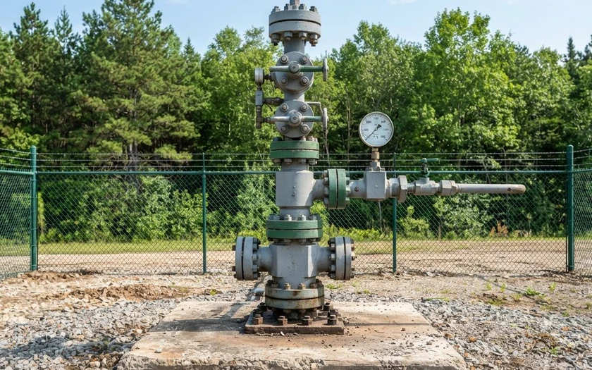
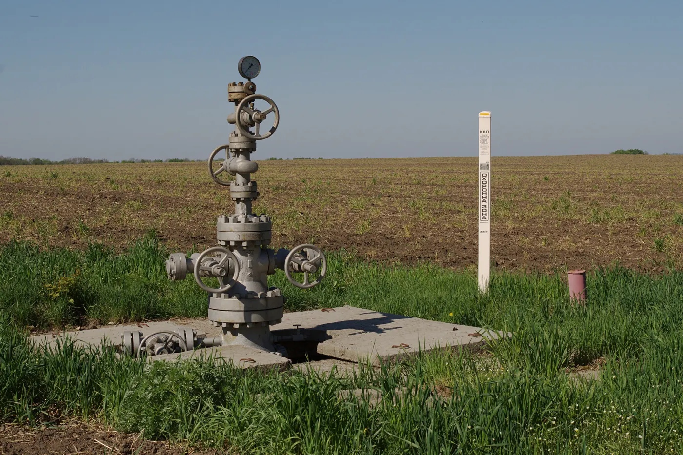
A freshly painted grey wellhead: a steel christmas tree of valves with a pressure gauge, on a concrete slab at the edge of a farm field
Fig. 15 · Wellhead footprintPhoto

Photo: ReAl · CC BY-SA 3.0

More than 90% of the CCUS chain is expected to be CCS with geological storage.

The objective of CCS is to keep industrial activity where it was built, optimize it and limit its CO2 emissions while greener technologies are developed over the next decades. This avoids delocalizing industry and simply transferring the pollution somewhere else, and it protects jobs, knowledge and technologies.

We also work closely with carbon capture companies so that geological storage is operated at full efficiency, bringing several CO2 sources under the same storage hub to take cost down. Our prospects are open for emitters to join when capacity is available.

PLATE 05Negative emissionsSHEET 05 / 09

Zero is not the ceiling.

Bioethanol, biomass power, waste incineration, pulp mills and sugar emit carbon that was in the atmosphere last season, not a hundred million years ago. The plant already pulled it down for you.

Cut that stream to zero and you have stopped adding. Send it a kilometre underground instead and the tonne leaves the cycle for good. That is a removal, not an avoided emission, and the two are not the same product.

It is the one case where storage does not take you to neutral. It takes you past it.

Talk about negative emissions
0 CO₂ EMITTED CO₂ REMOVED NO CAPTURE CAPTURE, THEN USE CAPTURE, THEN STORE BIOGENIC CO₂, THEN STORE
Fig. 16 · Each route against zeroPer tonne
PLATE 06Monitoring and safetySHEET 06 / 09

Every tonne, followed.

Ensuring the permanent containment of stored CO2 is the cornerstone of our mission. Without it, all our efforts to reduce emissions would be ineffective. Surveillance is comprehensive and customized to each storage site, across five spheres, and all results are shared as public information.

Geosphere

Protect rocks and uphold seal integrity.

Hydrosphere

Safeguard aquifers.

Biosphere

Protect flora and fauna.

Atmosphere

Prevent any CO2 surface leakage.

Well integrity

Ensure safe injection.

Confidence comes from the ground itself.

Our approach consists in tracking and controlling CO2 underground at all times. We draw confidence from natural CO2 reservoirs that have remained stable at various depths for millions of years.

Regulation, from both sides of the table.

We leverage our team's expertise in subsurface integrity delivered to regulators over more than ten years. We frame and follow the best regulation of Europe, North America, South East Asia and South America, and our safety approach is fully transparent so that all stakeholders can contribute to storage safety.
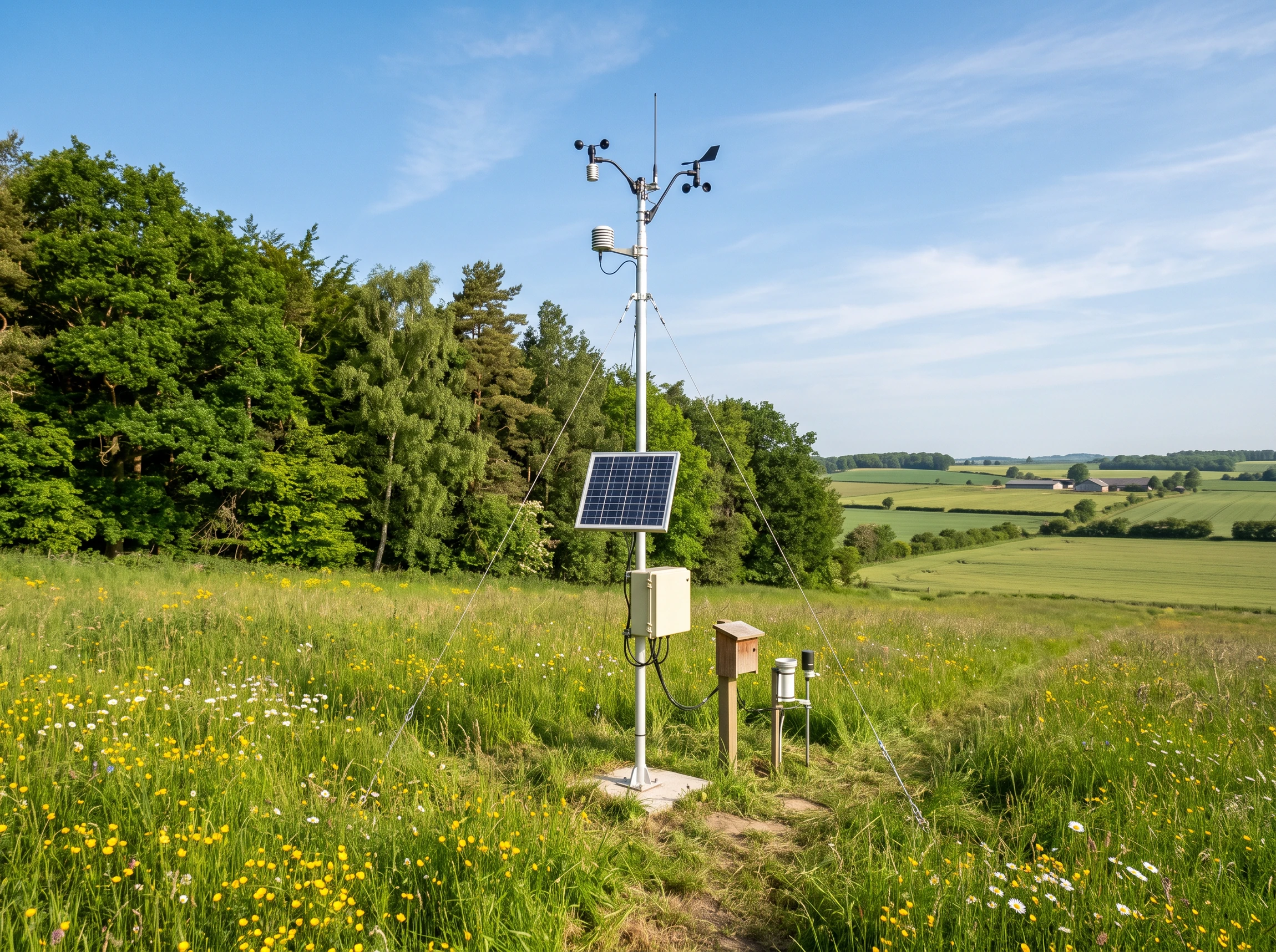
A monitoring station with sensors and a solar panel standing in a meadow beside a forest
Fig. 17 · Surface monitoring stationReference imagery
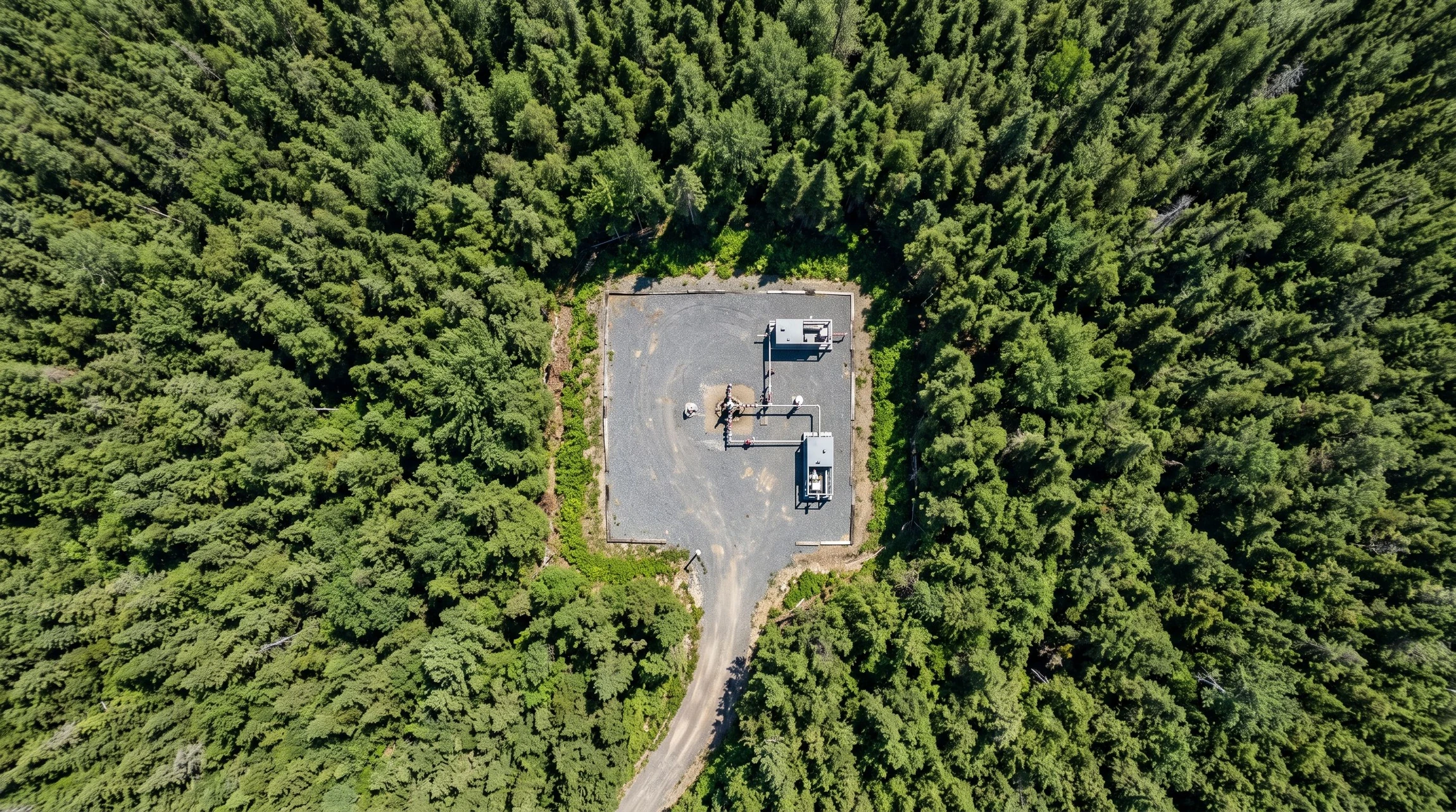
Straight down aerial view of a small rectangular gravel well pad in dense forest, a single wellhead and two skid units on it, one narrow access track
Fig. 18 · Storage site, surface footprint, from aboveReference imagery
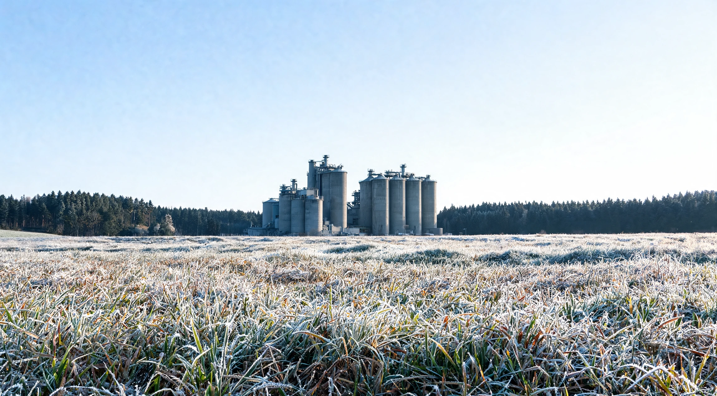
An industrial plant with concrete silos seen across a frosted field at the edge of a forest on a cold clear morning
Fig. 19 · The same site, watched through every seasonReference imagery
PLATE 07Track recordSHEET 07 / 09

Eleven countries,
already explored.

Our team has explored the subsurface in eleven countries, across the four regions we work in. The map marks each of them. Every marker is a country, not a site.

World map of the countries our team has explored Eleven countries are marked: Brazil in South America, Thailand and Indonesia in South East Asia, Australia, and in mainland Europe Denmark, France, Germany, Italy, Slovenia, Spain and Switzerland. The European markers are repeated in an enlarged detail below the world sheet. EQUATORDETAIL ABRAZILTHAILANDINDONESIAAUSTRALIAEQUIRECTANGULAR PROJECTION · COASTLINES SIMPLIFIEDANTARCTICA OMITTEDDENMARKGERMANYSWITZERLANDSLOVENIAITALYFRANCESPAINDETAIL A · EUROPE MAINLANDSCHEDULE · COUNTRIES EXPLOREDCOUNTRYREGIONAUSTRALIAAUSTRALIABRAZILSOUTH AMERICADENMARKEUROPE MAINLANDFRANCEEUROPE MAINLANDGERMANYEUROPE MAINLANDINDONESIASOUTH EAST ASIACOUNTRYREGIONITALYEUROPE MAINLANDSLOVENIAEUROPE MAINLANDSPAINEUROPE MAINLANDSWITZERLANDEUROPE MAINLANDTHAILANDSOUTH EAST ASIADETAIL A ENLARGED · STANDARD PARALLEL 47 NMARKERS INDICATE COUNTRIES, NOT INDIVIDUAL SITES
Fig. 20 · Where the team has exploredEleven countries
PLATE 08TeamSHEET 08 / 09

Get things done.
Stay transparent.

De-risking and sustainability, delivered by people who have spent their careers in the subsurface.

Vincent Geyl

Vincent Geyl

Subsurface leader, regulatory expert

LinkedIn
Leidiane Sampaio

Leidiane Sampaio

Geologist and geophysicist, R&D leader

LinkedIn
Leo Malouf

Leo Malouf

Drilling manager, renewable energy leader

LinkedIn
PLATE 09ContactSHEET 09 / 09

Send us your emissions.
We will tell you if the
ground can take them.

No exploration budget, no drilling commitment, no obligation. Just an answer about the rock under your site.

  1. 01You tell us where you emit and roughly how much.
  2. 02We screen the geology under and around you, at our cost.
  3. 03If it works, we carry the exploration risk and build the storage.

Direct line

contact@terrastora.com

Europe MainlandSouth AmericaSouth East AsiaAustralia

Please enter your first name.
Please enter your last name.
Please enter a valid email address.
Please enter your company.
Please tell us what you need.

Your details are used only to answer your enquiry.